PROJECT 03
Analysis of uplift resistance characteristics of expandable piles in sandy soil with varying wing inclination and dimensions
Status: Under review.
Air-supported domes transfer membrane and cable tension into their foundations. This study investigates how the dimensions and inclination of expandable pile wings affect uplift resistance in sandy soil, with a focus on the mechanisms of pile–soil load transfer.
Materials & Methods
Numerical model and study design
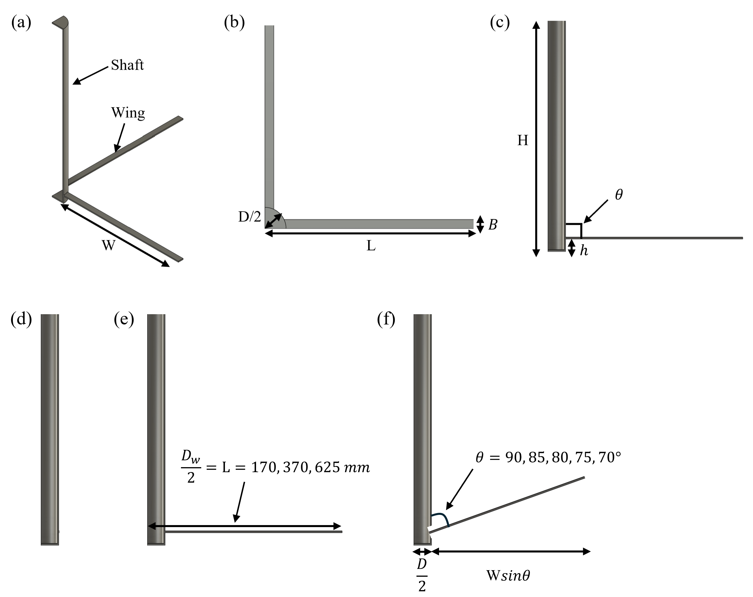
| Case | θ (°) | L (mm) | W (mm) | Dₑ (mm) | H/Dₑ | Dₑ/D | uₘₐₓ (mm) |
|---|---|---|---|---|---|---|---|
| Base | — | — | — | — | — | — | 5 / 7 |
| L-170 | 90 | 170 | 113 | 340.0 | 2.21 | 2.98 | 7 |
| L-370 | 90 | 370 | 313 | 740.0 | 1.01 | 6.49 | 7 |
| L-625 | 90 | 625 | 568 | 1250.0 | 0.60 | 10.96 | 7 |
| A-90 | 90 | 370 | 313 | 740.0 | 1.01 | 6.49 | 5 |
| A-85 | 85 | 370 | 313 | 737.6 | 1.02 | 6.47 | 5 |
| A-80 | 80 | 370 | 313 | 730.5 | 1.03 | 6.41 | 5 |
| A-75 | 75 | 370 | 313 | 718.7 | 1.04 | 6.30 | 5 |
| A-70 | 70 | 370 | 313 | 702.2 | 1.07 | 6.16 | 5 |
Common parameters: D = 114 mm; H = 750 mm; H/D = 6.58; four wings; B = 48 mm; h = 31 mm; shaft wall, toe plate and wing thickness = 4.5 mm. W = L − D/2. Dₑ denotes effective wing diameter; uₘₐₓ is maximum applied uplift displacement.
The X-Pile consists of a steel pipe shaft with four expandable wings near its tip. Three-dimensional quarter-symmetric models in Abaqus/Standard represent pile–soil interaction under calcareous-sand conditions representative of Abu Dhabi. The model uses Mohr–Coulomb soil, a rigid pile idealization, hard normal contact and Coulomb friction.
The analysis uses a fixed embedment depth of 750 mm and a shaft diameter of 114 mm. Two parameter series examine:
- Wing length: 170, 370 and 625 mm at a 90° shaft–wing angle.
- Wing inclination: 90°, 85°, 80°, 75° and 70° at a fixed 370 mm wing length.
Displacement-controlled uplift simulations provide resistance–displacement curves, wing and shaft resistance components, contact forces and soil plastic-zone distributions.
Results
Effects of wing length on uplift resistance and soil plastic zones
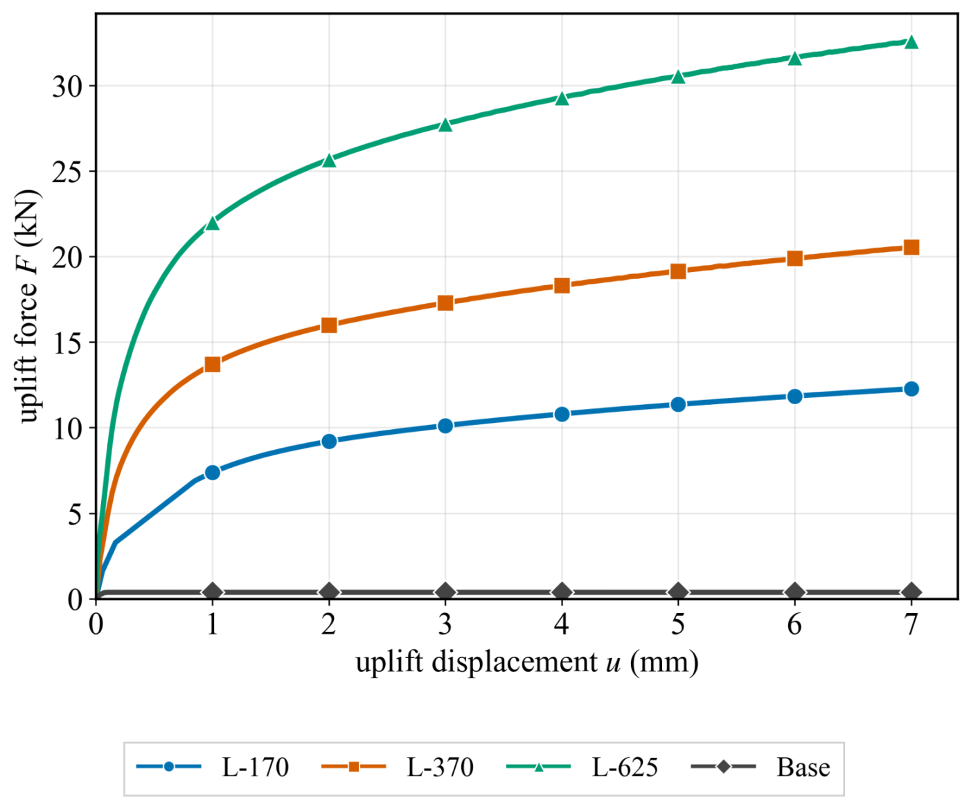
At 7 mm uplift, increasing wing length from 170 to 370 and 625 mm increased the simulated resistance from 12.27 to 20.54 and 32.59 kN, respectively. Wings provided 89.8–98.4% of the total resistance. The longer wings increased total resistance, although resistance per equivalent projected wing area decreased with wing size.
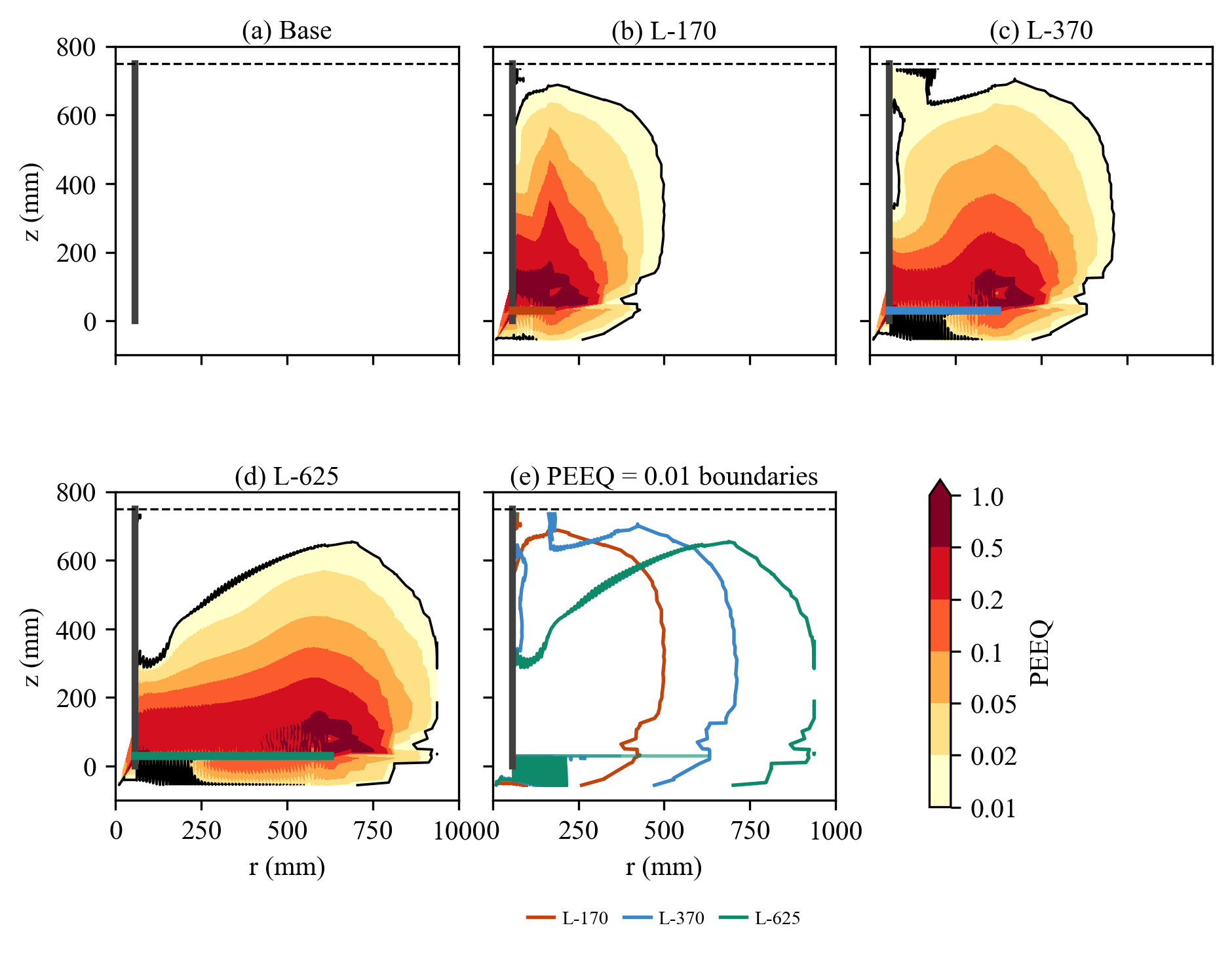
The unwinged Base pile developed almost no soil plasticity. Winged piles mobilised an upward and outward plastic zone. For L-170 and L-370, the zones extended close to the ground surface; L-625 produced a broader zone around the wing that terminated approximately 190 mm below the surface. Increasing wing size therefore changed both the resistance and the shape of the mobilised soil region.
Effects of wing inclination on uplift resistance and soil plastic zones
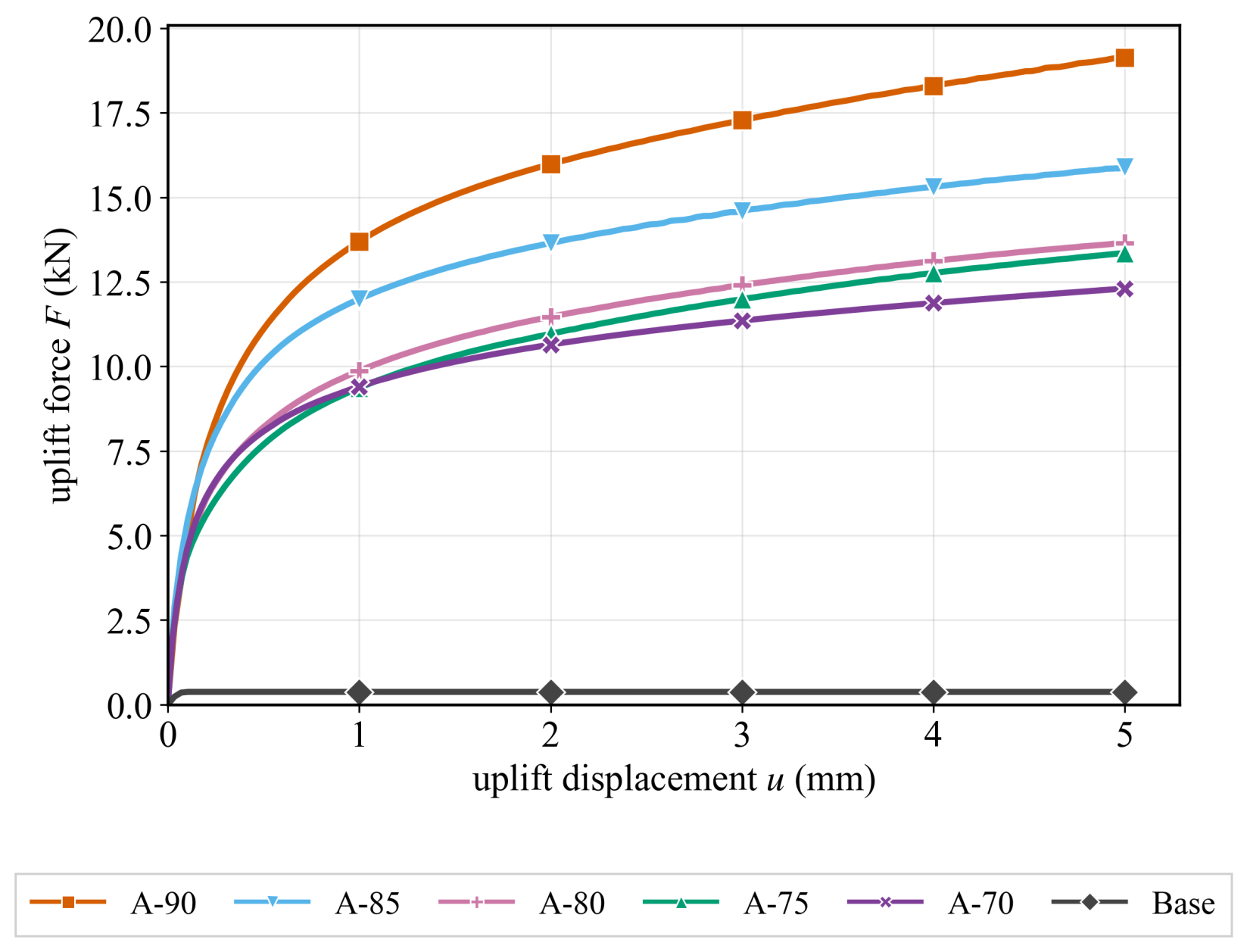
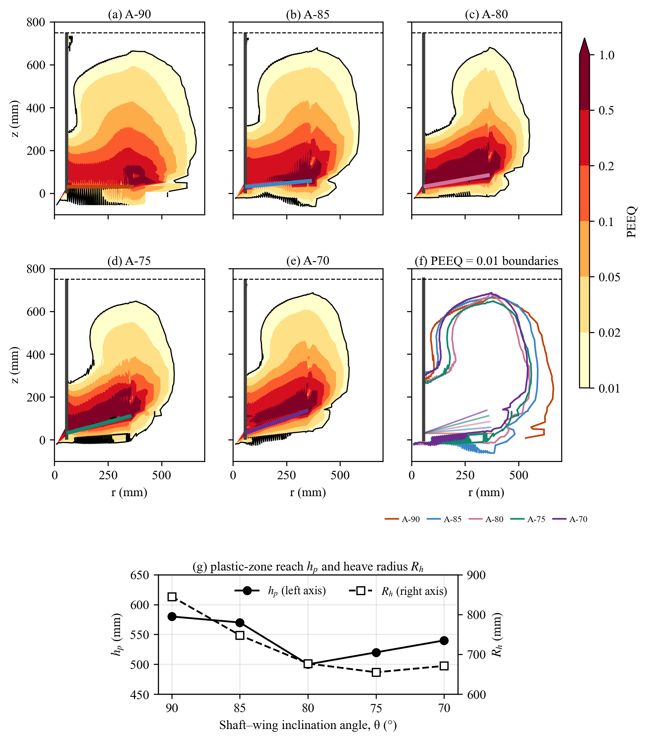
At 5 mm uplift, resistance decreased from 19.14 kN at 90° to 12.27 kN at 70°, a 35.9% reduction. The decline was nonlinear, with the largest relative drop occurring between 90° and 85°. The wing-surface normal resultant fell from 17.68 to 9.80 kN; the greater tangential contribution did not compensate for the loss of normal bearing resistance.
The plastic zone followed the inclined wing surface, and the upward wedge generally contracted as the angle decreased. Vertical reach remained below the horizontal-wing case without a monotonic trend. The ground-heave radius decreased from 845 mm at 90° to 671 mm at 70°, with a minimum of 655 mm at 75°. These changes accompany the reduction in simulated uplift resistance.
Funding
This work was supported by the Korea Institute of Planning and Evaluation for Technology in Food, Agriculture and Forestry (IPET) through the Agri-Food Export Enhancement Technology Development Program, funded by the Ministry of Agriculture, Food and Rural Affairs (MAFRA) (RS-2025-02313370).
Project title: Development of Commercial-scale Vertical Farming System with Low Energy Consumption Based on Passive Air-dome Technology for Hot Climate in Middle East
Research output
Analysis of uplift resistance characteristics of expandable piles in sandy soil with varying wing inclination and dimensions
Seokyung Park, Jaesung Park, Junbong Jang, Daniel Park, Sein Kwon, Minjoo Kim and Gaeun Choi.